
Test Points on EPC Space Evaluation Boards…Explained!!!

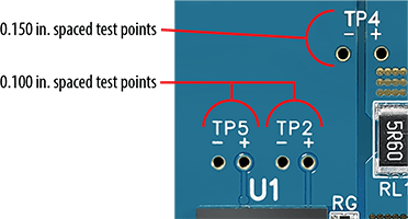
Customers who are presently putting EPC Space product demonstration boards through their paces have noticed that all the key signal measurement test points are implemented as a pair of 0.040” plated-through holes (PTH’s). In each case, each PTH pair has the signal (as represented by TP +) and the associated ground return (as represented by TP -). These test points have either 0.100” or 0.150” hole-to-hole spacing, depending upon the magnitude of the signal being measured (See Figure 1).
Why do we implement the holes instead of providing a probe tip adapter (PTA’s) or other connector-like accommodation for the oscilloscope’s probe tip? Some manufacturers provide PTA’s for their evaluation boards – are the folks at EPC Space just being cheap when it comes to this?
The reason for the implementation of the holes is twofold (and no, one is not that we are being cheap!!). The first reason is that the holes discourage the prospective data collector from using a probe with a “flying” ground lead and the second is that the various oscilloscope manufacturers have not standardized the diameter of their probe tips, which come primarily in 2.5, 3.5 and 5mm diameters.
Let us start with the problems and issues surrounding using the oscilloscope flying ground lead. This signal grounding arrangement produces distortions in high-speed signal(s) being measured due to the loop area presented by the ground lead, particularly in circuits where EPC Space products will find applications. Figures 2a, 2b and 2c show the difference between the unadulterated signal being measured, with a probe tip that uses a ground wire (~4.5”), and with a probe that uses a short/stub ground (less than 0.100” length), as intended to be used with the EPC Space evaluation board test points. It is obvious that the signal measured with the probe that uses the short ground connection most faithfully reproduces the signal in question, albeit with a short propagation delay that is characteristic of the probes being used, and some slight distortions due to even the shortest ground connection possible.
The resultant signal will never be a prefect replica of the original signal, as Figure 2c ably demonstrates, as some loop area is present even using the shortest wire-length ground possible. However, the result will be as close as we can get in this real-world that we live in.
Now, the reason for the distortion observed is because the long ground wire, although low resistance at low frequencies, becomes an inductor at high frequencies due to its non-zero loop area (blame Maxwell, Farady, Lenz and Ampere for this!). This parasitic inductance will interact with high edge/slew-rate signals to produce voltage disturbances at the ground sleeve on the barrel of the probe which is the reference location where the oscilloscope makes its measurements. High-speed digital logic and switching power supply circuits, where EPC Space eGaN® HEMT-based products are utilized, have signals present with VERY high slew rates. Measuring the signals in these circuits presents a particular problem and erroneous readings will occur if care is not taken when acquiring them, such as with the employment of the short, low inductance measurement grounds. There is another reason for using these short ground connections, particularly when evaluating switching power circuitry: large magnitude, high-frequency AC currents with high slew-rates and high-frequency magnetic fields from magnetic elements in close physical proximity to the probe ground loop area. In these situations, the inscribed probe ground loop becomes a receiving antenna and introduces electro-magnetically-induced signals onto the loop circuit formed by the ground lead, the probe tip capacitance and the impedance of the circuit being measured. The oscilloscope probe essentially becomes a near field signal probe!
The result is that if a long ground-leaded probe is used, untrustworthy and misleading signal measurements will be obtained and many an hour may be possibly spent chasing “problems” that do not exist in the circuit…or “fixing” problems that may harm the proper operation of the circuit in question. Hence EPC Space’s use of those probe holes!
Figure 2. Comparison of Signal Fidelity: Long Versus Short Ground Connections
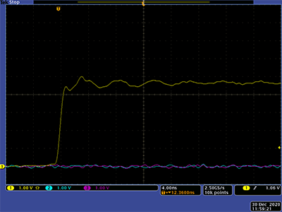
Vert: 1V/div
Horiz: 4ns/div
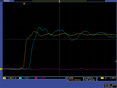
Vert: 1V/div
Horiz: 4ns/div
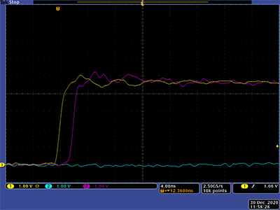
Vert: 1V/div
Horiz: 4ns/div
The second issue previously mentioned, the non-standardized PTA test points, presents a dilemma when designing the evaluation boards. Which PTA is the most popular? Which is available with reasonable lead times, if at all? Frankly, we would have to be really good guessers as to which PTA to use for ALL potential customers. So once again, the test point holes become a simple solution that allows ANYONE with an oscilloscope and probe to measure the signals on our evaluation boards!
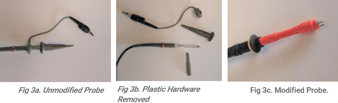
So, now that we’ve dealt with the why’s of the test probe holes, let’s take a look at the oscilloscope probe tip arrangement that should interface with the provided test point holes. Most oscilloscope probes come with a small kit of parts to adapt the probe for different measurement situations. Most of the time, these small, inscrutable parts become lost or misplaced…particularly those intended to reduce the length of the ground lead. And despite their efforts, the probe manufacturers don’t always achieve the desired short length. However, there is a simple, sure-fire, “home brew” way to hack a manufacturer-provided probe (Fig 3a) for the shortest ground lead possible:
- Remove all plastic hardware from the probe (Fig. 3b);
- Take a short (~3”) length of 20 AWG stripped solid copper wire and tightly wrap it 7-10 times around the exposed probe tip barrel’s ground sleeve, leaving ~0.25” extending beyond the tip. Cover the ground wire and exposed ground sleeve with heat shrink tubing, leaving ONLY the probe tip and new ground wire exposed, and shrink (Figure 3c). The color of the heat shrink tubing may be used to identify the various probes modified;
- Trim the new ground lead so it is approximately the same length as the probe tip.
Figure 3. Oscilloscope Probe Modified for Short Ground Connection
For wider spacings, a “jog” may be placed in the wire where it emerges from the heat shrink tubing to achieve the proper spacing desired.
Your newly modified probe(s) will find a home on all of EPC Space’s evaluation boards, as listed in Table I. These boards will allow the designer to explore and observe the benefits of our extensive product portfolio. Contact EPC Space to learn functionality, cost, and availability for each of these evaluation boards.
| EPC Space P/N | Description | Featured Products |
| EPC7C001 | FBS-GAM01P-PSE FBG04N30 Demo Board | FBS-GAM01P-PSE, FBG04N30 |
| EPC7C002 | FBS-GAM01P-PSE FBG10N30 Demo Board | FBS-GAM01P-PSE, FBG10N30 |
| EPC7C003 | FBS-GAM01P-PSE FBG20N18 Demo Board | FBS-GAM01P-PSE, FBG20N18 |
| EPC7C004 | FBS-GAM01P-PSE Parallel FSMD-B Eval. Board | FBS-GAM01P-PSE, FBG04N30 |
| EPC7C005 | FBS-GAM02-P-C50 POL Eval. Board | FBS-GAM02-P-C50 |
| EPC7C006 | EPCS-GAM02-P-C50 3-Phase Motor Control Motherboard/Eval. Board | FBS-GAM02-P-C50 |
| EPC7C007 | EPCS-GAM02-P-C50 Class-D Full Bridge Eval. Board | FBS-GAM02-P-C50 |
| EPC7C008 | GAM01-P-C50 Demo Board | FBS-GAM01-P-C50 |
| EPC7C009 | GAM01-P-C100 Demo Board | FBS-GAM01-P-C100 |
Table I. EPC Space Evaluation Board List

